In all phases of audio technology the decibel is used to express signal level differences. expressed by the same level, 10 dB. Any 10 dB level difference, regardless of the actual powers involved, will represent a 2-to-1 difference in subjective loudness. We will now expand our power decibel table: P1 (watts) Level in dB.
the decibel (abbreviated dB) is used to express differences between two values signal. The reason the decibel is such a useful measure is that it enables us to use a comparatively small range of numbers to express large and often unwieldy quantities. For convenience, we find the ratio between the two numbers and convert that into a logarithm. . If we measured one value as 10 watt and another as 1000 watt, we say that one is 20 dB greater than the other. If the softest audible sound has a power of about 0.000000000001 watt/sq. meter and the threshold of pain is around 1 watt/sq. meter, giving a total range of 120dB.
Power difference in dB = 10 log ( Power A / Power B)
The following tabulation illustrates the usefulness of the concept. Letting Power B = 1 watt:
Power A (watts) Level in dB
1 0
10 10
100 20
1000 30
10,000 40
20,000 43
The usefulness of all this becomes apparent when we think about how the ear perceives loudness. The decibel also makes sense from a psychoacoustical point of view in that it relates directly to the effect of most sensory stimuli. First of all, the ear is very sensitive. In the second place, our judgment of relative levels of loudness is somewhat logarithmic. If a sound has 10 times the power of a reference (10dB) we hear it as twice as loud. If we merely double the power (3dB), the difference will be just noticeable.
Converting voltage or pressure ratios to decibels
Remember that the dB is used to describe relationships of power. Power is not often conveniently measured, especially in electronic devices. We can use voltage, current, and pressure ratios as they relate to power. Most often we measure voltage and use the formula P = E2/Z to get power. Squaring a value doubles its logarithm, so our dB formula becomes:
Power divergence in dB = 20 log (voltage A / voltage B)
We now present a table useful for determining levels in dB for ratios given in voltage. Letting Voltage B = 1 volt:
Voltage A Ratios Level in dB
1 0
1.25 2
1.60 4
2 6
2.5 8
3.15 10
4 12
5 14
6.3 16
8 18
10 20
Sound Pressure Level (SPL)
For decibels of sound pressure level (SPL), the reference is the extremely low value of 20 x 10-6 newtons/m2. This reference pressure corresponds roughly to the minimum audible sound pressure for persons with normal hearing. SPL ranges from 0 dB SPL (the threshold of hearing), to above 120 dB SPL (the threshold of pain). Conversational speech is about 70dB SPL. A change of 1 dB is about the smallest SPL difference that the human ear can detect, while 3 dB is a generally noticeable step, and an increase of 10 dB is perceived as a “doubling” of loudness. As a convenient point of reference, note that an rms pressure of 1 pascal corresponds to a sound pressure level of 94 dB. We commonly use a sound level meter (SLM) to measure SPL
Aug 25, 2006
Decibels
Aug 23, 2006
Directional Characteristic of a Microphone
The directional characteristic of a microphone is defined as the variation of its output when it is oriented at different angles to the direction of the sound. It determines how best to place the microphone relative to the sound source(s) in order to enhance pickup of desired sound and to minimize pickup of undesired sound.
Many people have the misconception that microphones only pick up sound from sources they are pointed at, much as a camera only photographs what is in front of the lens. This would be a nice feature if we could get it, but the truth is we can only approximate that action, and at the expense of other desirable qualities.
The polar pattern of a microphone is the graphical representation of the output produced vs. the angle of the sound source. The output is represented by the radius of the curve at the incident angle. The two most common directional types are omnidirectional and unidirectional.
Omnidirectional Microphone
A omnidirectional is simplest microphone design that will pick up all sound, exhibits the same output regardless of its orientation to the sound source. This indicates that the microphone is equally sensitive to sound coming from all directions.
An omnidirectional microphone can therefore pick up sound from a wide area, but cannot be “aimed” to favor one sound over another. Generally have good to outstanding frequency response.
Unidirectional Microphone
A unidirectional microphone is most sensitive to sound coming from only one direction. On a polar graph, this will appear as a rounded but noncircular figure.
Unidirectional microphone may be aimed at a desired, direct sound by orienting its axis toward the sound until the output of a unidirectional microphone is maximum for sound arriving at an angle of 0 degrees, or on-axis. It falls off only slightly for sound arriving from within a certain angle off-axis. For any microphone, the direction of least sensitivity (minimum output) is called the null angle. it may also be aimed away from an undesired, direct sound by orienting its null angle toward the sound. The total directional range for usable output is called the coverage angle or pickup area.
In addition, a unidirectional microphone picks up less ambient sound than an omnidirectional, due to its overall lower sensitivity at the sides and rear. The most common type of unidirectional microphone is called a cardioid, because of its heartshaped polar pattern.
Cardioid Microphone
A cardioid type is most sensitive to sound coming from in front of the microphone (the bottom of the “heart”). On the polar graph this is at 0 degrees, or “on-axis”. It is less sensitive to sound reaching the microphone from the sides (“off-axis”), and the direction of least sensitivity is toward the rear (the notch at the top of the “heart”). For a cardioid pattern, this is at 180 degrees or directly behind the microphone. Coverage angle for a cardioid microphone is about 130 degrees. A cardioid picks up only one-third as much ambient sound as an omnidirectional type.
Supercardioid and the Hypercardioid Microphone
Compared to a cardioid type, supercardioid and the hypercardioid have a progressively narrower coverage angle: 115 degrees for a supercardioid and 105 degrees for a hypercardioid. However, unlike the cardioid, they have some pickup directly behind the microphone. This is indicated in their polar patterns by a rounded projection, called a lobe, toward the rear of the microphone. The direction of least sensitivity (null angle) for these types is about 125 degrees for the supercardioid and 110 degrees for the hypercardioid. In general, any directional pattern that has a narrower front coverage angle than a cardioid will have some rear pickup and a different null angle. The supercardioid has the maximum ratio of on-axis pickup to ambient pickup, while the hypercardioid has the least overall pickup of ambient sound (only onequarter as much as an omni). These can be useful types for certain situations, such as more distant pickup or in higher ambient noise levels, but they must be placed more carefully than a cardioid to get best performance. The Hypercardioid pattern is very popular, as it gives a better overall rejection and flatter frequency response at the cost of a small back pickup lobe.
A "shotgun" mic carries these techniques to extremes by mounting the diaphragm in the middle of a pipe. The shotgun is extremely sensitive along the main axis, but posseses pronounced extra lobes which vary drastically with frequency. In fact, the frequency response of this mic is so bad it is usually electronically restricted to the voice range, where it is used to record dialogue for film and video.
Bi-directional Microphone
bidirectional type. As the name implies, it is equally sensitive to sound from two directions: directly in front of the microphone and directly behind it. Its polar graph consists of a front pickup area and an identical rear lobe and resembles a “figure 8” pattern. Although the front coverage angle of a bidirectional microphone is only 90 degrees, it has equal rear coverage. The null angle is at 90 degrees, which is directly at the side of the microphone. While the bidirectional microphone is not used by itself in any typical house of worship sound application, it is occasionally used in combination with other types for stereo sound reproduction.
Aug 22, 2006
Frequency Response of Microphones
There is no inherent advantage in fidelity of one type of microphone over another. Condenser types require batteries or power from the mixing console to operate, which is occasionally a hassle, and dynamics require shielding from stray magnetic fields, which makes them a bit heavy sometmes, but very fine microphones are available of both styles. The most important factor in choosing a microphone is how it sounds in the required application.
The frequency response of a microphone is defined by the range of sound (from lowest to highest frequency) that it can reproduce, and by its variation in output within that range. It is the frequency response that determines the basic “sound” of the microphone.
The two general types of frequency response are flat and shaped. These terms refer to the graphical representation of frequency response or response curve. A microphone that provides a uniform output at every audible frequency is represented on a frequency response graph as an even, flat line, and is said to have a flat response. This means that the microphone reproduces all of the sound within its frequency range with little or no variation from the original sound. In addition, flat response microphones typically have an extended frequency range; that is, they can reproduce very high and/or very low frequencies as well. Widerange, flat response microphones have a natural, highfidelity, “uncolored” sound.
Flat Frequency Response
A flat frequency response has been the main goal of microphone companies for the last three or four decades. In the fifties, mics were so bad that console manufacturers began adding equalizers to each input to compensate. This effort has now paid off to the point were most professional microphones are respectably flat, at least for sounds originating in front. The major exceptions are mics with deliberate emphasis at certain frequencies that are useful for some applications. This is another part of the microphone mystique. Problems in frequency response are mostly encountered with sounds originating behind the mic.
By contrast, a shaped microphone response will appear on a frequency response graph as a varying line with specific peaks and dips. This shows that the microphone is more sensitive to certain frequencies than to others, and often has a limited frequency range. A shaped response is usually designed to enhance the sound of a particular source in a particular application, while at the same time minimizing the pickup of certain unwanted sounds. Shaped response microphones each have a “characteristic” sound.
Shaped Frequency Response
The selection of a flat or shaped response microphone involves consideration of both the sound source and the sound destination. The frequency range of the microphone must be wide enough to pick up the desired range of the sound source. This range must also be appropriate to the intended destination of the sound: that is, wider range for high-quality sound systems or recording/broadcast systems, narrower range for speechonly public address systems. Within its range the microphone should respond in such a way that the sound is reproduced either with no change (flat response) or with changes that enhance the sound in some desirable manner (shaped response). 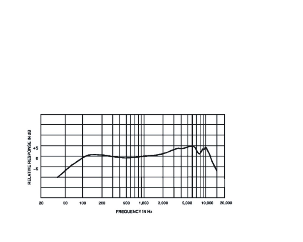
Normally, microphones with flat, wide-range response are recommended for high-quality pickup of acoustic instruments, choral groups and orchestras, especially when they must be placed at some distance from the sound source. Flat response microphones are less prone to feedback in high gain, distant pickup applications because they do not have frequency response peaks that might trigger feedback at any specific frequency. The most common shaped response is for vocal use. Typically, this consists of limiting the range to that of the human voice and adding an upper mid-range response rise. Such a “presence rise”, coupled with controlled low- and high-frequency response can give a sound with improved vocal clarity. This is especially true for lapel or lavalier microphones. The pickup of certain instruments such as drums and guitar amplifiers may also benefit from a shaped response microphone. Finally, the frequency response of some microphones is adjustable, typically by means of switches, to tailor the microphone to different applications. Most common are low-frequency rolloff controls, which can help prevent “rumble”, and presence rise switches to enhance
intelligibility.
Aug 21, 2006
Dynamic and Condenser Microphones
A microphone is an example of a transducer, a device that changes energy from one form into another, in this case, acoustic energy into electrical energy. Sound information exists as patterns of air pressure; the microphone actually picks up this sound information and converts it into patterns of electric current. The recording engineer is interested in the accuracy of this transformation, a concept he thinks of as fidelity.
A variety of mechanical techniques can be used in building microphones. These are the two most common types of microphones in the world:
Dynamic microphones
Dynamic microphones are the type most widely used in live sound, which refers to the design of the microphone capsule. This type are economical and rugged, with fairly low sensitivity, good for handheld or "close-miked" applications. Dynamics microphones are commonly used for solo vocalists and on drum kits. They can provide excellent sound quality and good specifications in all areas of microphone performance. In particular, they can handle extremely high sound levels: it is almost impossible to overload a dynamic microphone.
Dynamic microphones employ a diaphragm/voice coil/magnet assembly which forms a miniature sounddrivenelectrical generator. Sound waves strike a thin plastic membrane (diaphragm) which vibrates in response. A small coil of wire (voice coil) is attached to the rear of the diaphragm and vibrates with it. The voice coil itself is surrounded by a magnetic field created by a small permanent magnet. It is the motion of the voice coil in this magnetic field which generates the electrical signal corresponding to the sound picked up by a dynamic microphone.
Condenser microphones
Condenser microphones are typically (but not always) much more sensitive than dynamics and can provide a smoother, more naturalsound, particularly at high frequencies. Flat frequency response and extended frequency range are much easier to obtain in a condenser. In addition, condenser microphones can be made very small without significant loss of performance. Typically used for recording orchestras, choirs, and in other applications where you wish to capture the sound of the ensemble, versus individual sounds.
It's inline frame from http://audiofarmers.blogspot.com
